
See this post for details.
Creating a Custom LED Module for the Panasonic RC-7462
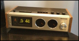 The Panasonic RC-7462 features twin, AM/FM speedometer-like FM/AM tuning dials, a fine sounding 4 inch speaker (for a vintage flip clock), real wood side panels and a relatively large flip clock mechanism with fluorescent digits. The clock originally came with a 3 inch black light tube that reportedly (per a magazine advertisement) provided "sharp and clear" illumination without glaring light. However, finding this clock with a working blacklight is not likely in this era. The two clocks used in a recent restoration by flipclockfans.com both had tubes with some purple glow left, but not enough to even lightly illuminate the digits of the flip clock.
Initially trying a blacklight 6 LED 42 mm festoon bulb in a restored RC-7462 produced adequate results, but the bulb did not fully illuminate the digits. Also, when wired into the 12 volts provided by the circuit board, the light would pulsate when music was played moderately to loudly.
The Solution:
Devise a custom LED module with as few LEDs as possible, wired in parallel to the circuit board.
How To Make Your Own Custom LED Module (Black Light!)
Materials needed
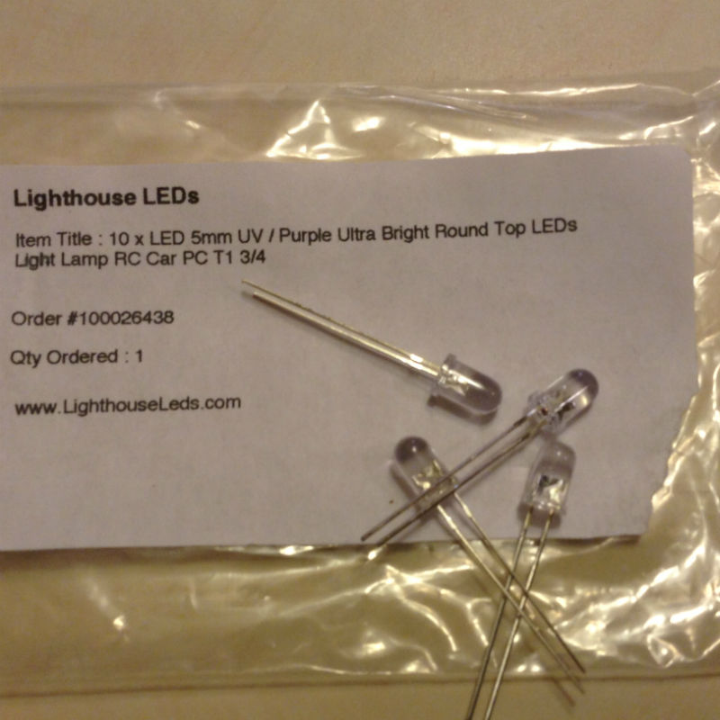
4 - 5mm UV/Purple Ultra Bright Round Top LEDs
(wavelength of around 400nm or less) - try lighthouseleds.com
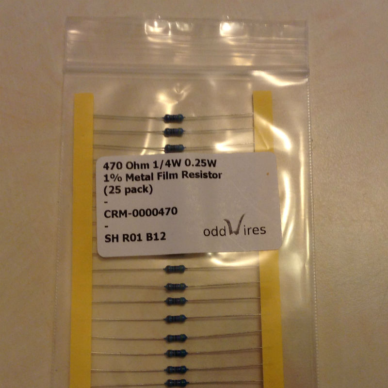
4 - 470 Ohm 1/4 (0.25) Watt Resistors (metal film recommended).
Ours purchased from eBay seller "Oddwires"
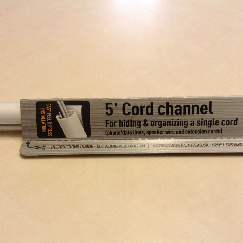
1 - Cord Channel (for hiding and organizing an electric cord)
rounded, flat bottomed with no more than a 1/2 inch diameter
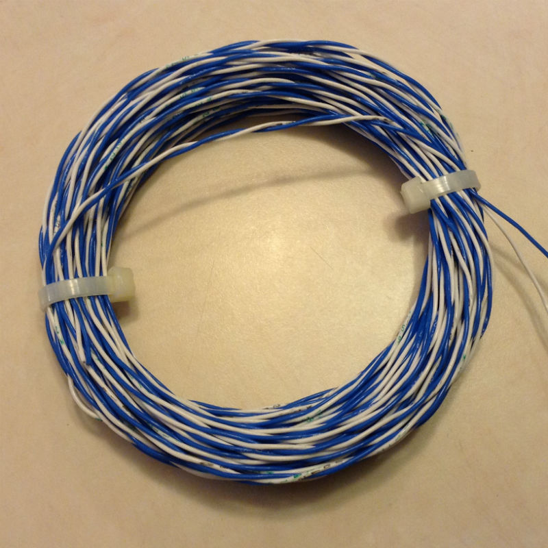
4 - 10 inch lengths of twisted pair 24 AWG stranded wire (or 4 lengths of two
different colors of wire to differentiate between + and -
(we went overboard with Thermax - Teflon insulated, silver-plated 19 stranded copper wire).
1 - 3/16 inch drill bit (and drill if needed)
1 - razor blade/utility knife
1 - wire stripper tool of your choice
1 - soldiering iron and soldier
1 - ruler
1 - tape measure
1 - cutting device (hacksaw, or Dremel with cutting wheel).
The Materials - Easily available from various internet and hardware sources
Part One: The Module Housing
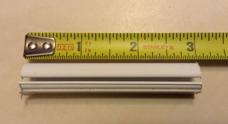 - cut a 3 inch length of the cord channel with your saw, Dremel or other tool.
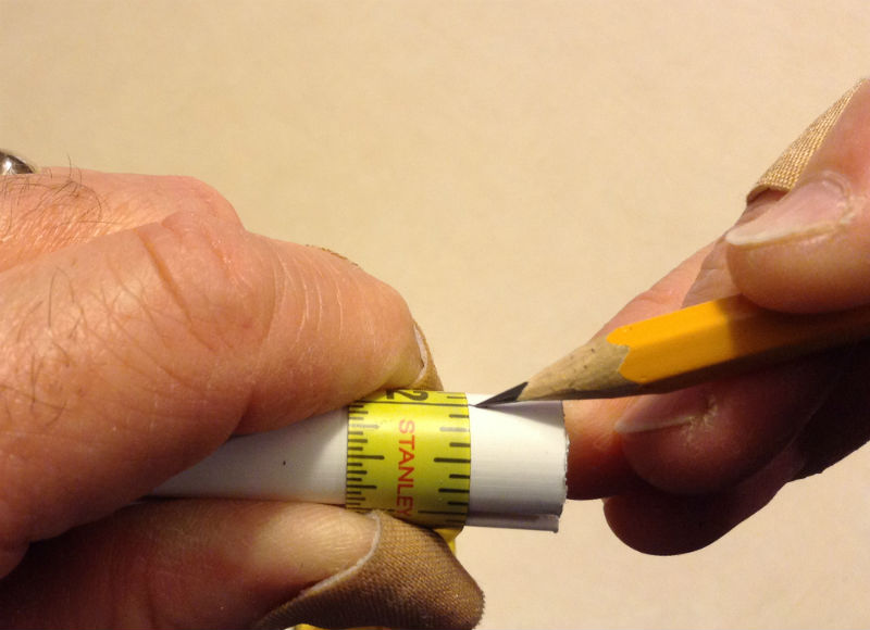
- drill holes to accept the LEDS: To obtain the correct angle of lighting, you need to measure 1/2 inch from the top of the wire channel on what will be the back of our module or, 1/2 inch from the base at the front (right where the flat spot ends). You'll need to wrap a tape measure right up against the cord channel to get a proper and consistent measure. This alignment was obtained from much trial and error and using a prototype. If your cord channel is not the same as that listed/pictured, you will almost certainly have to alter this measurement. Mark the 1/2 in off at a few spots and connect the dots with pencil using a straight edge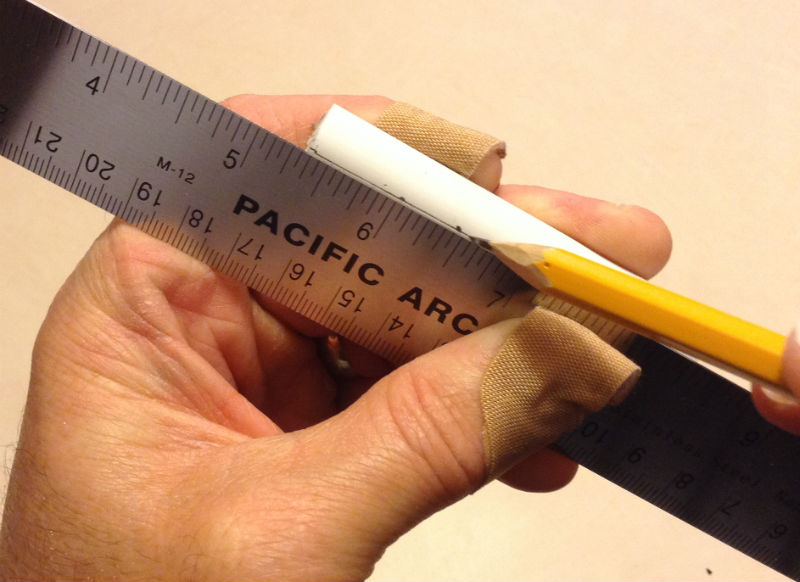
- Mark off the four points where you will drill your holes for the LEDS: Again, the following measures were developed for these particular LEDs after many trials. With the front facing you (the part opposite the open channel), mark off points from left to right as follows: 5/8 in, 1 1/4 in, 2 in and 2 1/4 inch.
The initial 5/8 inch mark works because the module will be butted up against the available space in the cabinet, 5/8 inches over being the optimal spot to illuminate the last minute digit and correctly align the remaining holes for each digit flap. If you choose not to do this, you need to make two holes with their centers 1/2 inch apart, a space of 7/8 inch, then two more holes centers 1/2 inch apart.
 - (recommended - not required) using a new, sharp razor blade point, start making the hole for the drill bit by placing the point right on the dot and rotating back and forth creating a pilot hole. Drilling on a curved surface is very difficult!
- Drill holes at each point marked off. The cord channel plastic is usually relatively soft, and it's possible to drill the hole out by hand holding the bit (wrapped in a bit of Gorilla tape). However, if you have a steady hand, use a drill! The LEDs will require just a bit more room than the 3/16 inch affords. Place a round file in each of the holes or use the drill bit and score out a little more room. You can test the holes but pushing a LED in from the outside. Try to get it where it just fits snugly but does not require excessive force (you'll have to push these up from the inside of the cord channel and you don't want to have to push too hard.
Part Two: The LEDs
- For these steps, you'll need to be familiar with soldiering. Don't take this for granted. There are many fine tutorials for basic soldiering - there are tricks to it. Also we'll need to become aware of the + and - sides of the LEDs. You cannot get these mixed up. The positive side (also known as the anode) will have a longer leg. The negative side (known as the cathode) will have a shorter leg, of course, but the LED base has a flat spot on that side (helpful if your LED legs are cut ... and they will be shortly). Pick a wire color for your + and the other will be for your -. Do not mix these up it must be the same for all bulbs. Cut the legs of the LED down to about 3/8 inch, strip off about 1/4 of the insulation from your wires. Tin the stripped ends (this is basic soldiering talk - remember Google and YouTube are your friends) then soldier the proper colored wire to the correct leg of the LED. This is where remembering that the negative side has a flat spot near it helps. Do this with all bulbs. Separately insulate each leg of the two legs of the LED with heat shrink tubing of a small size. Do this to all four bulbs.
- In a later step we will soldier one of the 470 Ohm resistors towards the end of each of the + (anode) wires.
NOTE: placing the resistor on the anode side is the convention. You could as well put it on the cathode or - side, but not both! pick one or the other and keep it the same for each LED. You'll notice on many tutorials and pictures of prepared LEDs that the resistor is often connected right to the LED leg itself. That's just fine, but for this purpose, it was decided that the resistors would be placed towards the end of the anode wires. This frees up space for wires in the module, makes it easer to get the LEDs in the holes and also could minimize heat build up inside our module.
Part Three: Fabricate the Module
Load up the prepared cord channel with LEDs. This is where the shortened LED legs and the fact that the resistors will not be on the LEDS helps.
 There's not much room inside the cord channel. Bend the legs to one side and fit the first LED into the side of the last marked hole. In other words, start with the hole drilled at the 2 1/4 spot. The wires will be allowed to trail out from this side. After you get the first one in, go to the next hole and so on. It will take some work and a small screw driver or similar tool to press the LEDs into the holes from the inside of the channel. The fact that this cord channel has an opening in the back makes this process much easier than it would have been otherwise. Take your time and be careful. If you notice that you can see some of the legs of the LEDs under the heat shrink tubing after you bend the legs to one side, don't worry. These will have nothing to come into contact with once in place inside the channel.
Separate the different colored wires into two groups - the positive and the negative. On the positive (anode) ends, cut all the wires about two inches up from the shortest wire. You see, the wires will be all different sizes due to being in the cord channel at different locations. Strip the ends of the wires
 about 1/4 inch. Trimmed back each wire end of the resistors until there remains about 1/2 inch or so on either side. Soldier one of these resistors to each end of the four anode wires. Take the left over wire that you cut from the anode wires, strip and soldier a piece to the other end of the resistor. Cover the soldiered wires and the whole resistor with heat shrink insulation tubing. At this point, cut off all the anode wires so that they're the same length. Strip each end and twist and soldier them together. All of these will be connected to 12 volt D/C positive. Do the same to the negative leads - of course, these are to be connected to the negative side of your power source.
NOTE: The LEDs are not visible once the cabinet top is in place. It looks fantastic.
Congratulations: You now have a module that will fit perfectly into the Awesome, Panasonic RC-7462 - The Black Lighted Flip Clock. Testing reveals very good illumination of the digits and no pulsing with the music.
Update: 12/23/2017 - There is a better way now.
See this post for details.
Full page ad from the magazine, "New York" October 16, 1972
The first thing you see in the morning shouldn't be an ugly face. 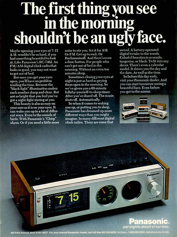
Maybe opening your eyes at 7:15 A.M. wouldn't bee so hard, if you had something beautiful to look at. Like Panasonic's RC-7462. An FM/AM digital clock radio that looks so good, you may not want to get out of bed.
But once you get your eyes open, you'll have no problem reading the time. Because the "black-light" illumination makes each number sharp and clear. But not so bright that you feel you've got a night light staring at you.
This beauty is also as easy on your ears as it is on your eyes. It can wake you up in a lot of different ways. Even to the sounds of birds. with Panasonic's "Chirp" alarm. Or if you need a little more noise to stir you. Set it for AM. Or FM. Get up to rock. Or Rachmaninoff. And there's even a doze button. For people who can't get out of bed in the morning. Without an extra ten minutes sleep.
Sometimes closing your eyes at night is just as hard as prying them open in the morning. So we've given you a 60-minute lullaby-yourself-to-sleep-timer. After you've dozed off. The music shuts off. Automatically.
So when it comes to waking you up, or putting you to sleep, Panasonic has dreamed up more different ways than you might imagine. In many different digital clock radios. There are some that swivel. A battery-operated digital to take to the woods. Colorful beauties in avacode, tangerine, or black. To fit into any decor. There's even a calendar model. It shows you the day and the date. As well as the time.
So before this day ends, visit your Panasonic dealer. And you can start tomorrow seeing a beautiful face. Even before you get to the mirror.